Cameras in OpenGL
16 Apr 2020A feature that almost every game has and uses is a camera. But how is a camera represented in game code? In this blog post I will explain how cameras work in OpenGL, and provide a simple explanation with some visuals of how you can set up a camera.
Cameras in Game Development
Once again, cameras are commonly used in game development to let the player “view” the scene. There are two main types of cameras that you can use, perspective and orthographic, and they are used for 3D games and 2D games respectively. The main difference in these cameras is the way that the player percieves the game world. In a perspective projection, objects that are further away from the camera appear smaller in size, just like in real life. Whereas, in an orthographic projection, objects appear the same no matter the distance from the camera. The image below demonstrates the difference between these projections.
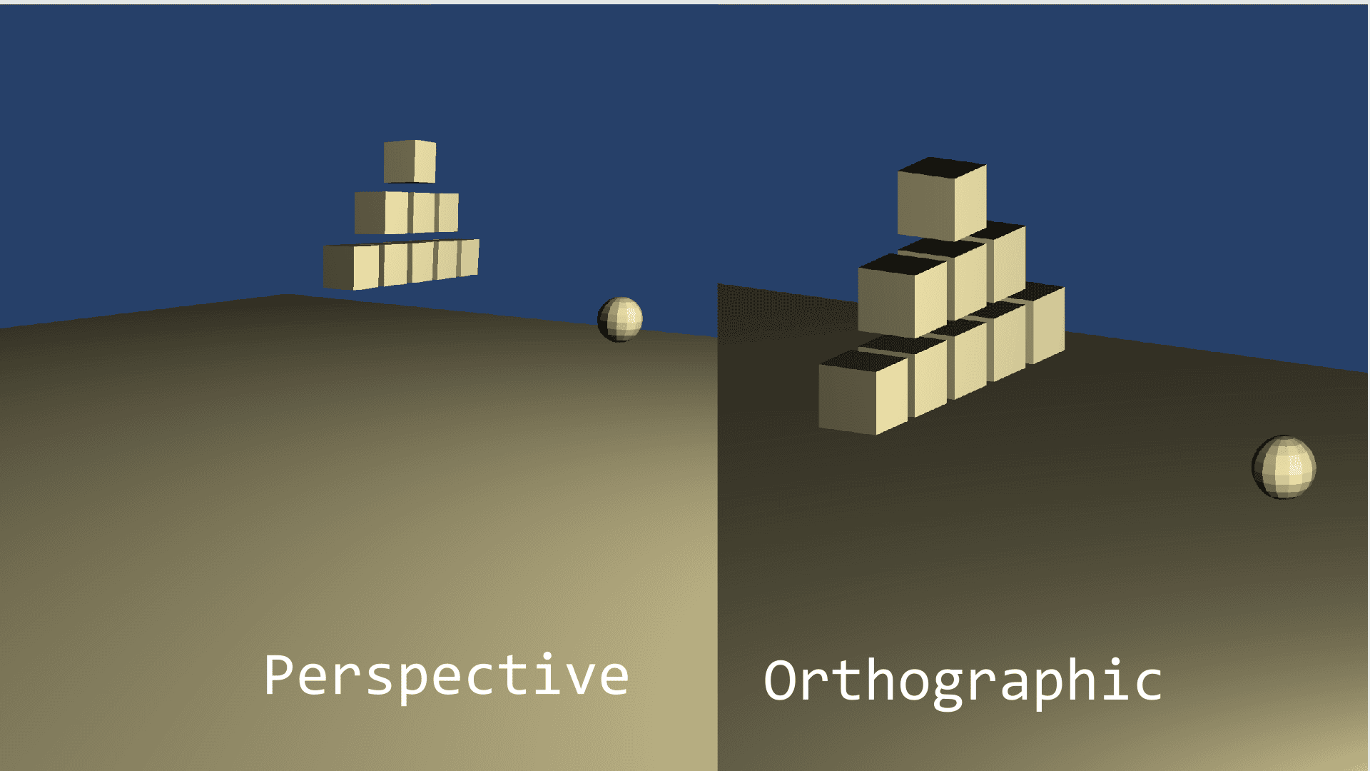
As you can see, there is no perception of depth in the orthographic projection. This makes it ideal for 2D games, where you want a layered approach to drawing things. Since there is no distortion as objects are placed further away from the camera, you can draw 2D sprites that you want behind other sprites, further back. Think of this the same way layers work in Photoshop.
Now, to get a camera set up for your game, there are two things that you will need, the projection matrix, and the view matrix. The projection matrix defines whether or not you have a perspective, or orthographic projection, and how it will map to your game world. The view matrix defines where the camera is in world space, and where it is pointing. We will discuss these in further detail below.
The Projection Matrix
The first step that you would want to do to set up your Camera class in OpenGL, is define your projection matrix. Once again, this is simply setting up a mathematical function that will make your objects either have depth, or not have depth. The example I will show uses JOML, but this will translate very similarly to other Math libraries such as GLM.
Matrix4f perspectiveProjection = new Matrix4f().identity();
Matrix4f orthoProjection = new Matrix4f().identity();

perspectiveProjection = perspectiveProjection.perspective(fov,
    aspectRatio, 0.1f, 100000.0f);

orthoProjection.ortho(0, 1920, 0, 1080.0f, 0.5f, 100.0f);
This bit of code sets up two matrices that will define this camera’s projection matrix. I have listed an example that shows how you would set up a perspective matrix, and an orthographic matrix so you can see the differences.
The documentation that JOML provides for these two functions are listed here for the perspective function and here for the ortho function. What you can see is that each of them take in a different set of parameters. Let’s go through each of the parameters and see what the math library is using to set up the Matrices.
Matrix4f.perspective()
This function takes in 4 floats, they are documented as fovy, aspect, zNear and zFar respectively. Each of these is used to build an appropriate perspective. The fovy is used to define the field-of-view in degrees, which basically defines how warped the perspective is. The higher this number is, the more of a fish-bowl look your game will have. A good number for this is typically 45, because that’s close to what we see in real life.
The aspect is the aspect ratio you want your camera to have, this will typically contain the same aspect as the player’s window, so 16:9 for an HD monitor, or 4:3 for a tablet, etc. The last values are the zNear and zFar clipping planes. These values determine how close an object can be to the camera before disappearing (zNear) and how far away an object has to be from the camera before disappearing (zFar). As you can see, I chose 0.5 and 100000.0 for these values. I chose these because 0.5 is the closest I want my camera to ever get to an object, and you can typically set the zFar to an arbitrarily large number without any performance penalties for reasons that are beyond the scope of this article.
Matrix4f.ortho()
This function takes 6 floats, they are documented as left, right, bottom, top, zNear, zFar. The first four values define the dimensions of your camera’s view frustum. This basically means that any objects in your scene that are between these values will be seen by the camera. As you can see I chose the values 0, 1920, 0, 1080 for an HD projection. This means that any Game Object that is in my scene that’s x-value is between 0-1920 and y-value between 0-1080 will show up in my camera. The zNear and zFar values are used for the same thing as the perspective function.
The View Matrix
The next thing we need, is a view matrix. The view matrix is literally just the position of the camera in world space, and the direction it is pointing. This is important, because we need both to be able to find out what objects we need to render. Let’s look at some code that is typically used to set this up.
Vector3f cameraForward = new Vector3f(1, 0, 0);
Vector3f cameraRight = new Vector3f(0, 0, 1);
Vector3f cameraUp = new Vector3f(0, 1, 0);

// Position would be defined somewhere else, it is simply
// the position of the camera in world space
Vector3f center = new Vector3f(position.x, position.y, position.z);
center.add(cameraForward);

this.viewMatrix.identity();
this.viewMatrix = viewMatrix.lookAt(transform.position, center, cameraUp);
As you can see in the code, I define three vectors for the cameraForward, cameraRight, and cameraUp. These are all unit vectors, meaning they all have a length of 1. This will help us to define the direction the camera is pointing in. Then, we have the center variable. This is a point in world space that the camera is looking towards. These are all required for JOML’s lookAt function that we use to create the view matrix. The documentation is listed here.
The function takes three variables, the eye, center and up. These three vectors are used to create the view matrix. The eye is the camera’s position, the center is a point that the camera is looking towards, and up is what direction the top of the camera is facing. Let’s see what these look like visually.
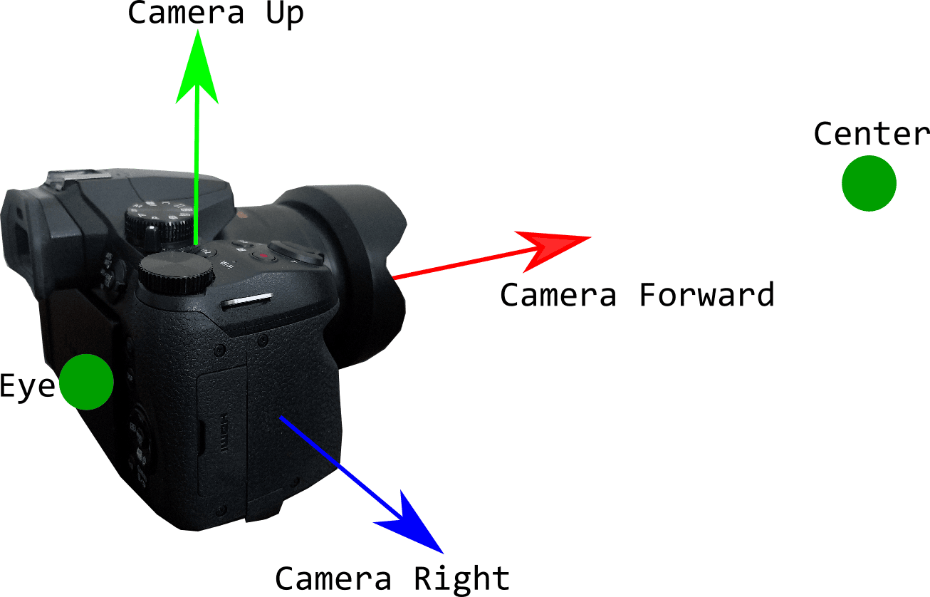
In the image, we can clearly see that the center is just some point that is directly in front of the camera, and the eye is the position, and so on and so forth. This means that if we change any of the vectors, we will change the entire direction of the camera. Lets try an example, if we change the camera’s up vector from the current vector to: cameraUp = new Vector3f(1, 0, 0); the resulting configuration of our camera will look like this:
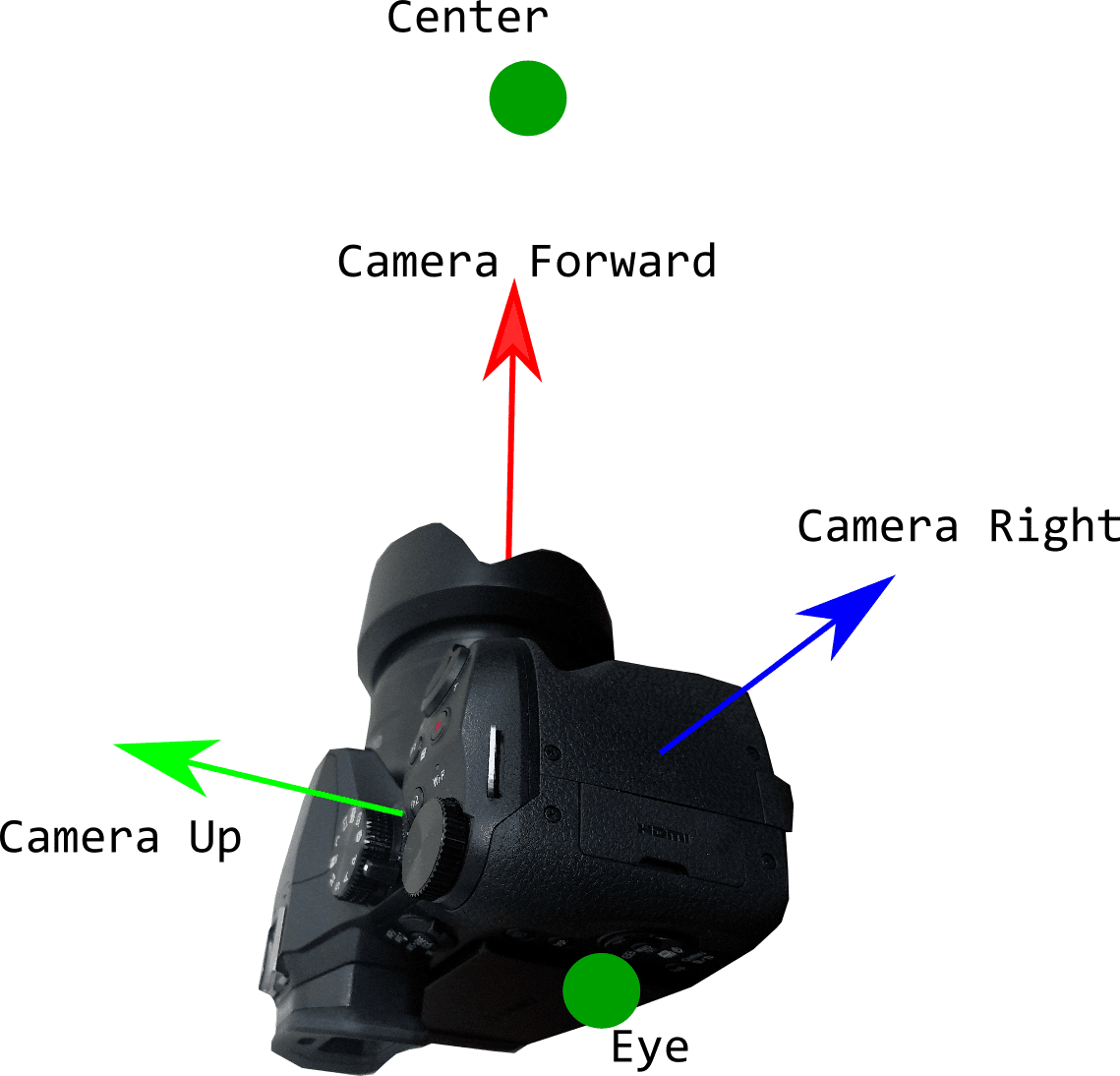
Now we have our camera facing an entirely different direction, all by changing one simple vector! In reality, you would also have to change your eye vector, and center vector to match the new configuration of the camera. By the way, this view matrix will work for 2D orthographic projections as well. Typically, in a 2D scenario, you would want a fixed view matrix for your camera, where the camera is pointed towards the xy plane as the first picture shows. Then, you can draw all your sprites on the xy plane, and the camera will always be pointing towards the correct direction.
Conclusion
I hope this article gave you a good high-level overview of how cameras work in OpenGL. If you want a more concrete implementation of a camera, I highly recommend this article. It is in C++, but the concepts are showed extrordinarily well. If you have any questions or comments, feel free to leave them below!
Thanks for reading!